A technical deep dive into flange geometry, point selection, coating systems, and installation variables that separate reliable connections from field failures.
Abstract
Few fasteners carry as much structural responsibility with as little visible recognition as the Hex Flange Head Self Drilling Screw. From metal roofing and cladding to solar mounting and light structural steel, this screw must drill, tap, and clamp in a single pass—often in wind, rain, and corrosive exposure. This article examines the engineering logic behind the integrated flange head, the point-number system that governs material thickness compatibility, the coating technologies that determine service life, and the installation variables most often mismanaged in the field. It is written for contractors, distributors, and specification writers who need more than a catalog listing: they need a working understanding of why this fastener performs, and how to keep it performing across demanding construction environments.
Table of Contents
- Design Anatomy: Why the Flange Changes the Load PathJump to section
- Standards, Sizes, and the Point-Number SystemJump to section
- Coating Selection: Matching the Screw to the ExposureJump to section
- Installation Science: Speed, Pressure, and Seal CompressionJump to section
- Failure Modes That Trace Back to Selection and TechniqueJump to section
- Quality Assurance and Inspection ProtocolsJump to section
- Frequently Asked QuestionsJump to section
1. Design Anatomy: Why the Flange Changes the Load Path
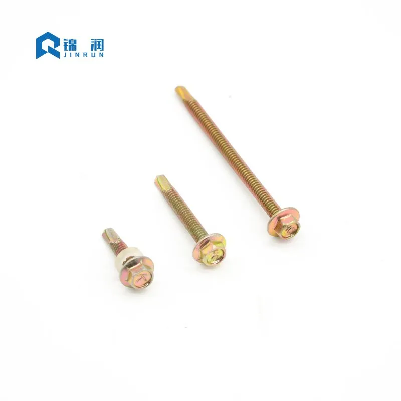
A conventional hex washer head relies on a separate steel-backed neoprene or EPDM washer to distribute clamping pressure. The flange head integrates that bearing surface directly into the head geometry. The result is not simply convenience. It changes how force travels through the connection.
The flange increases the bearing area under the head, which lowers contact stress on thin-gauge steel and pre-painted cladding. A lower contact stress reduces the risk of dishing, coating fracture, and pull-through when the connection is exposed to wind uplift or thermal cycling. Because the bearing surface is machined or cold-formed as part of the head, there is no separate washer to shift off-center, fall away during installation, or compress unevenly.
The hexagonal drive is equally functional. It accepts a standard socket or nut driver and transfers torque with far less cam-out than a Phillips or Pozi recess. That matters when the screw is expected to drill through a purlin and then clamp a panel without spinning the drive recess or stripping the head. For high-volume work, the combination of flange bearing and hex drive allows a single tool—typically a clutch-equipped screw gun—to drive thousands of fasteners to a consistent depth.
The Integrated Bearing Surface
When specifying fasteners for thin-gauge steel, the stress distribution under the screw head is a critical engineering consideration. A standard flat washer can bend or deform under high torque, compromising the integrity of the joint. The integrated flange on the Hex Flange Head Self Drilling Screw is designed with a specific thickness and diameter ratio that resists bending. This rigid bearing surface ensures that the clamp load is spread evenly across the connected materials. In applications involving insulated panels, the flange prevents the screw head from pulling through the relatively soft outer skin of the panel, maintaining a weather-tight seal even under dynamic wind loads.
Hex Drive vs. Cruciform Recesses
The choice of drive type significantly impacts installation efficiency and joint reliability. Cruciform recesses, such as Phillips or Pozi, are designed to cam out when a certain torque threshold is reached—a feature originally intended to prevent over-tightening in mass production. However, in construction applications where self-drilling screws must cut through steel, cam-out is highly undesirable. The hex drive provides a secure, six-point engagement that allows the operator to apply the necessary torque to drill the hole and tap the threads without the bit slipping. This positive engagement reduces operator fatigue, minimizes bit wear, and ensures that the full torque is transferred to the cutting edge.
Thread Geometry and Engagement
The thread profile of a self-drilling screw is optimized for both cutting and clamping. The threads are typically rolled rather than cut, which aligns the grain structure of the steel and increases strength. The pitch and major diameter are engineered to provide sufficient pull-out resistance in the receiving material. Fine threads are generally used for metal-to-metal applications, offering a higher number of threads per inch for greater holding power in thin sections. Coarse threads are often preferred for wood-to-metal or composite materials, where a larger thread depth is needed to displace the material without causing it to split or crumble.
- Integrated bearing surface: spreads clamp load without a loose washer.
- Hex drive: higher torque transfer and reduced bit slip under load.
- Self-drilling point: eliminates a separate drilling step in steel-to-steel connections.
- Precision thread roll: supports consistent engagement and pull-out resistance.
2. Standards, Sizes, and the Point-Number System
The global fastener market recognizes this product under several naming conventions—DIN 7504K, AS/NZS 3566, and IFI inch-series equivalents—but the underlying variables remain consistent: diameter, length, thread pitch, head geometry, and drill-point capacity. A supplier’s catalog may list dozens of combinations, but the specification decision usually reduces to two questions: what total thickness must be joined, and what point number can drill that thickness before the threads engage.
The point-number system is the single most important selection variable and the one most frequently misapplied. A Point #2 is intended for light-gauge sheet metal. A Point #3 covers the broad middle of general construction. A Point #5 is required for heavy structural plate. If the unthreaded drill point is shorter than the combined material stack, the threads begin to bite before the tip has exited the bottom layer. The result is jacking: the two layers are forced apart, thread engagement is compromised, and the screw may snap from torsional overload.
| Point Number | Typical Metal Thickness Capacity | Common Use Case |
|---|---|---|
| Point #1 | Up to 0.062 in (≈ 1.6 mm) | Ultra-thin sheet metal, HVAC ductwork |
| Point #2 | Up to 0.110 in (≈ 2.8 mm) | Light-gauge sheet metal, thin cladding |
| Point #3 | 0.110 – 0.210 in (≈ 2.8 – 5.3 mm) | General construction, roofing, steel framing |
| Point #4 | 0.210 – 0.250 in (≈ 5.3 – 6.4 mm) | Medium structural steel, heavy framing |
| Point #5 | 0.250 – 0.500 in (≈ 6.4 – 12.7 mm) | Heavy structural beams, thick plate |
Decoding DIN and IFI Equivalents
Metric and inch series do not always map one-to-one across suppliers. DIN ST4.8, ST5.5, and ST6.3 diameters correspond to common light and medium structural connections; IFI #10, #12, and #14 diameters serve the North American market. A specification that works in one series cannot be assumed interchangeable in the other without checking point length, thread pitch, and head bearing diameter together. For instance, a DIN ST5.5 screw might have a slightly different thread pitch compared to an IFI #12 screw, which can affect the engagement in pre-tapped holes or the driving torque required.
Length Selection and Material Stack Calculations
Length selection follows a practical rule: the threaded portion should extend at least three full threads beyond the joined material. That margin protects pull-out strength and accommodates minor variation in material thickness. When the stack includes insulation, sealant, or an uneven gap, the point must be long enough to clear the full stack before thread engagement begins. Engineers should always calculate the total material thickness (including any gaskets or washers) and add a minimum of 1.5 times the screw diameter to determine the minimum nominal length required.
3. Coating Selection: Matching the Screw to the Exposure
A fastener’s mechanical design determines whether it can make the connection. Its coating determines whether that connection survives. The same screw geometry can be supplied with electroplated zinc, hot-dip galvanizing, zinc-aluminum flake coatings, or multi-layer ceramic systems, and the difference in salt-spray performance is not incremental—it is categorical.
Standard electroplated zinc provides basic protection for indoor and mildly sheltered outdoor conditions. In coastal air or industrial atmospheres, that coating can show red rust within months. Hot-dip galvanizing offers a thicker sacrificial zinc layer for severe outdoor and marine environments, but the coating thickness can affect thread fit and requires careful handling at installation.
Electroplated Zinc and its Limitations
Electroplated zinc is the most common and economical finish for self-drilling screws. It provides a uniform, thin coating that does not significantly alter the thread dimensions, ensuring smooth installation. However, the standard zinc plating is relatively thin, often in the range of 5 to 15 microns. In environments with high humidity, salt spray, or industrial pollutants, the zinc layer is consumed rapidly. Once the zinc is depleted, the underlying carbon steel begins to corrode, leading to structural weakening and unsightly rust streaks on the building facade.
Hot-Dip Galvanizing for Severe Environments
For applications requiring long-term durability, hot-dip galvanizing (HDG) is a preferred choice. The HDG process involves dipping the screw into molten zinc, creating a metallurgical bond that results in a thick, abrasion-resistant coating. The zinc-iron alloy layers provide excellent sacrificial protection. However, the thick coating can make the threads slightly heavier, requiring the use of over-tapped nuts or specific driving techniques. HDG is ideal for heavy structural steel connections, outdoor fencing, and marine environments.
Advanced Zn-Al-Ceramic Systems
Ruspert-type zinc-aluminum-ceramic systems represent a different approach. The coating is a composite: a zinc sacrificial layer, an aluminum barrier layer, and an inorganic ceramic topcoat that seals micro-pores. Neutral salt-spray data for these systems commonly cite red rust resistance beyond 1,000 hours, compared with roughly 72–120 hours for conventional zinc plating. For roofs, facades, and solar arrays that cannot be readily maintained, that performance gap is the difference between a serviceable assembly and a premature replacement.
The Hex Flange Head Self Drilling Screw is frequently evaluated on coating performance alone, but the specification should treat coating, substrate, and environment as a single system.
| Coating Type | Relative Corrosion Protection | Indicative Salt-Spray Performance | Best-Fit Environment |
|---|---|---|---|
| Electroplated zinc | Basic | ≈ 72 – 120 hours | Indoor, dry, mildly sheltered |
| Hot-dip galvanized | High | Thickness-dependent, substantial | Severe outdoor, marine |
| Zinc-aluminum flake (Dacromet-type) | High | Several hundred hours | Industrial, automotive, coastal |
| Zn-Al-ceramic (Ruspert-type) | Very high | Red rust > 1,000 hours | Coastal roofing, chemical plants, unmaintainable surfaces |
Galvanic Corrosion and Dissimilar Metals
Coating selection is also a material-compatibility decision. A zinc-plated carbon steel screw in contact with an aluminum panel can create a galvanic couple in the presence of moisture. The less noble metal corrodes preferentially, and the resulting red rust streaks are both a durability and an aesthetic failure. In coastal zones and on aluminum assemblies, stainless steel bodies, bi-metal construction, or barrier coatings are the appropriate specification—not a heavier zinc layer on the same carbon steel substrate.
4. Installation Science: Speed, Pressure, and Seal Compression
Self-drilling screws are metal-cutting tools, not wood screws. They operate within a defined speed and feed window. Outside that window, the point overheats, work-hardens the steel, or fails to bite. The difference between a clean hole and a burned tip is usually a matter of RPM and downward pressure, not fastener quality.
For standard carbon steel screws, the productive range is generally cited between 1,500 and 2,500 RPM. Stainless steel self-drilling screws require lower speeds—often 1,000 to 1,500 RPM—because the material work-hardens and retains heat. When the point turns too fast without sufficient feed pressure, friction raises the tip temperature beyond the tempering range. The point turns blue, loses hardness, and stops cutting. The screw then spins without penetrating, and the installer often increases speed further—accelerating the failure.
Tooling Selection for Consistent Results
The tool matters as much as the speed. A clutch-equipped screw gun with a depth-sensitive nosepiece delivers consistent seating. A high-torque impact driver, by contrast, applies uncontrolled hammering and torque; the head can shear off just as the flange seats, or the EPDM washer can be crushed before the operator reacts. For any application involving a sealing washer, torque control is not optional. The use of a depth-sensitive nosepiece ensures that every screw is driven to the exact same depth, compressing the washer perfectly regardless of operator fatigue.
The EPDM Washer Compression Window
On roofing and cladding, the bonded EPDM washer is the primary water seal. It has a narrow correct compression range. Over-compression forces the rubber to mushroom beyond the metal backing, exposing it to UV degradation and tearing the rubber-to-metal bond. Under-compression leaves the washer loose, allowing capillary action to draw moisture beneath the head. A correct installation shows the EPDM slightly visible at the edge of the metal washer, with the metal backing flat or gently concave—not bowed upward.
Downward pressure is the other half of the feed-rate equation. Light “feathering” pressure at high RPM causes the point to rub and skate rather than cut. Steady, linear force—roughly 25 to 35 lb in many field guides—keeps the cutting edges engaged and produces curled metal chips. Fine metallic dust and a blue tip are signs of friction, not cutting. Curled chips indicate the heat is leaving with the chip rather than accumulating in the screw.
5. Failure Modes That Trace Back to Selection and Technique
Most field failures attributed to “bad screws” are actually specification or installation failures. Understanding the mechanism behind each failure shortens the diagnostic process and prevents repeat incidents.
Jacking and Thread Stripping
As described in the point-number section, jacking occurs when thread engagement begins before the drill point exits the bottom material. The layers separate, the threads strip in the upper sheet, and the screw may snap at the head. The correction is a longer point, not a larger diameter or a higher torque setting. Inspecting the hole after removal can reveal whether the threads were engaged prematurely.
Walking and Surface Damage
A screw that skates across the panel before biting scratches the zinc or paint coating and creates a corrosion initiation site. Walking is common when a point is too large for thin sheet, when initial pressure is too light, or when the bit is worn. A sharper point for thin gauge and firm starting pressure resolve most cases. In some situations, using a pilot punch or a specialized drill point for thin metal can eliminate walking entirely.
Head Snapping and Torque Overload
Head shear is a torque-limit failure. Impact drivers and worn clutches are frequent contributors. The screw may reach the seating surface and then receive a torque spike that exceeds the head-to-shank transition strength. A depth-sensitive nosepiece or a torque-limited screw gun prevents the spike. Ensuring the correct drive bit size is also crucial, as a loose-fitting bit can cause the corners of the hex drive to round off, requiring excessive force to remove.
Coating Degradation and Interface Corrosion
Dissimilar metal contact in a moist environment creates a galvanic cell. The damage appears as rust staining, coating blistering, or section loss at the interface. The remedy is material selection: stainless steel, bi-metal construction, or an appropriate barrier coating matched to the panel material and the exposure category. Regular visual inspections during construction can identify areas where coatings have been damaged during installation, allowing for touch-up before the structure is commissioned.
Each of these failure modes reinforces the same principle: the Hex Flange Head Self Drilling Screw is a system component. Point number, coating, substrate, tool, and technique must be selected together. A high-performance coating cannot compensate for an undersized point, and a premium screw cannot survive an impact driver with no depth control.
6. Quality Assurance and Inspection Protocols
Ensuring the reliability of connections in demanding construction projects requires a robust quality assurance process. Specifiers and contractors should implement inspection protocols that cover both the incoming fasteners and the finished installation.
Dimensional Verification
Incoming fasteners should be sampled to verify critical dimensions: head diameter, flange thickness, major and minor thread diameters, and point length. Variations in these dimensions can affect the screw's ability to drill effectively and clamp securely. For instance, an undersized flange might not provide adequate bearing area, leading to panel deformation. A shorter-than-specified point length can cause jacking in thicker material stacks.
Coating Thickness Testing
For projects in corrosive environments, verifying the coating thickness is essential. Magnetic induction gauges can be used to non-destructively measure the thickness of zinc or zinc-alloy coatings. Alternatively, laboratory testing of sacrificial coupons can confirm the salt-spray performance and adherence of the coating. Ensuring that the coating meets the specification is the only way to guarantee the expected service life.
Mechanical Property Validation
The mechanical properties of the screw—such as torsional strength and hardness—are critical for self-drilling applications. Torsional strength testing determines the maximum torque the screw can withstand before the head shears off or the shank twists. Hardness testing verifies that the drill point is adequately hardened to penetrate the target steel without dulling, while the core remains tough enough to resist brittle fracture. Suppliers like JINRUN typically provide certification of these properties based on batch testing.
7. Frequently Asked Questions
How do I know which point number to use for a given material thickness?
Can I use an impact driver to install these screws?
What causes a self-drilling screw to “walk” across the panel before drilling?
Is a Ruspert-type coating worth specifying over standard zinc plating?
Why do some installed screws show rust streaks within a few months?
For buyers and specifiers who need documented dimensional and coating options, the engineering team can provide detailed specifications and test reports. The critical step is to define the material stack, exposure category, and tooling before the order is placed—not after the first connection fails.
The flange head, the point number, and the coating are not independent features. They are a single specification decision. When they are aligned with the application, the Hex Flange Head Self Drilling Screw delivers the combination that keeps demanding construction assemblies together: drilling speed, clamping stability, and corrosion resistance in one operation.
Whether the next project involves metal roofing, solar mounting, or light structural steel, the right starting point is a technical conversation about material thickness, exposure, and installation method. Contact us to align the fastener specification with the application before the first screw is driven.
Contact Us for Project Support